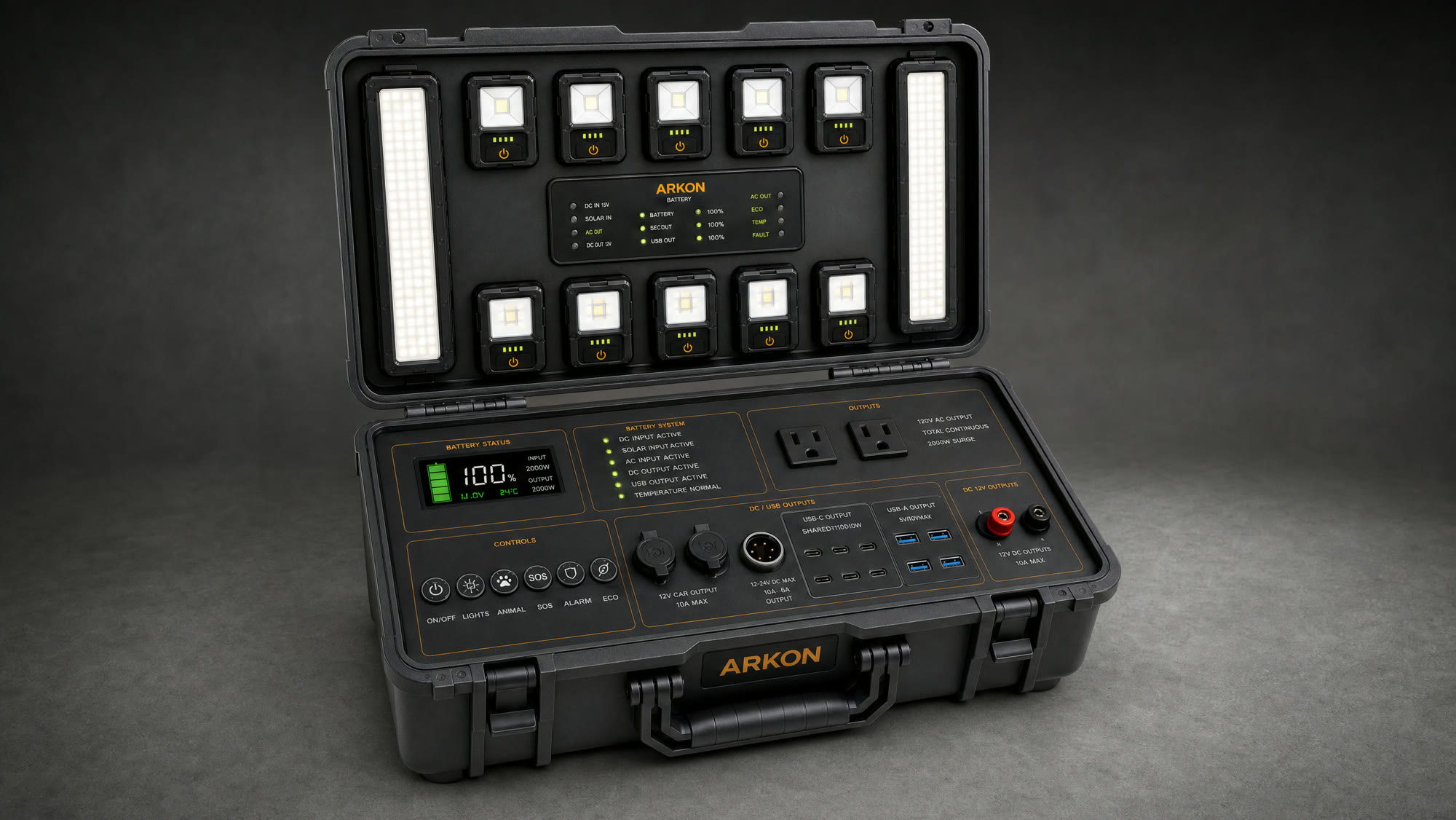
What we have built, what we are testing, and what is still ahead.
ARKON is in engineering validation. This page publishes the full specification set, the hardware detail, the tests we run before certification and the dates each stage is expected to close. Everything here is updated as the build progresses.
Images on this page are product visualizations of the current design intent. Production hardware may differ cosmetically, and performance figures are prototype targets until DVT and certification are complete.
The full number set, published before launch.
Energy storage
- Chemistry
- LiFePO4 (LFP), prismatic cells
- Capacity
- 1,024 Wh nominal
- Rated cycles
- 3,000+ cycles to 80% capacity (target)
- BMS
- Integrated protection: over-current, over-voltage, over-temp, cell balancing
- Self-discharge
- Designed for long standby storage between uses
Power output
- AC inverter
- 1,200 W continuous · 2,400 W surge, pure sine
- AC outlets
- 2 × 120 V
- USB-C
- 6 ports, PD — up to 100 W per high-power port, system-managed budget
- USB-A
- 4 × USB 3.0 fast charge
- DC
- 12 V outputs on the control deck
- Display
- State of charge, time remaining, AC/DC load, temperature
Lighting system
- Modules
- 10 removable square light modules
- Floodlights
- 2 vertical floodlight bars in the lid
- Deployment
- Modules detach and run independently, then recharge in the lid
- Control
- Deck-mounted rotary and button controls
Enclosure
- Format
- Rugged carry case, carry-on scale
- Sealing
- Gasketed lid — no vents or air intakes in the sealed body
- Charging inputs
- AC input and dedicated solar input (MC4 → XT60 cable)
- Weight
- Target figure locked after DVT
Target values are locked after DVT and certification. Where a figure is still under validation we say so instead of publishing a number we cannot yet defend.
Every subsystem, up close.
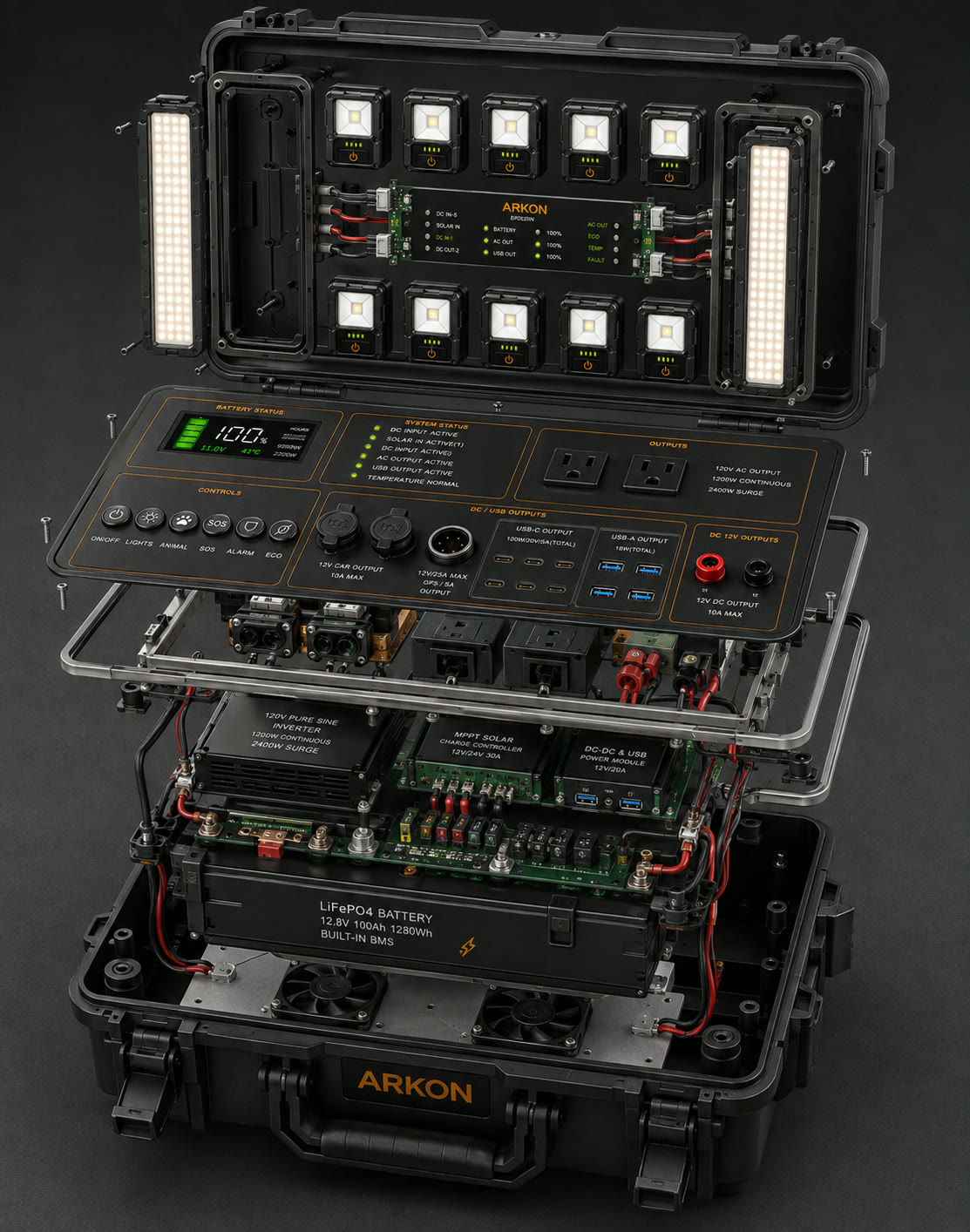
Pack, inverter, control deck and lid lighting array as separate assemblies.
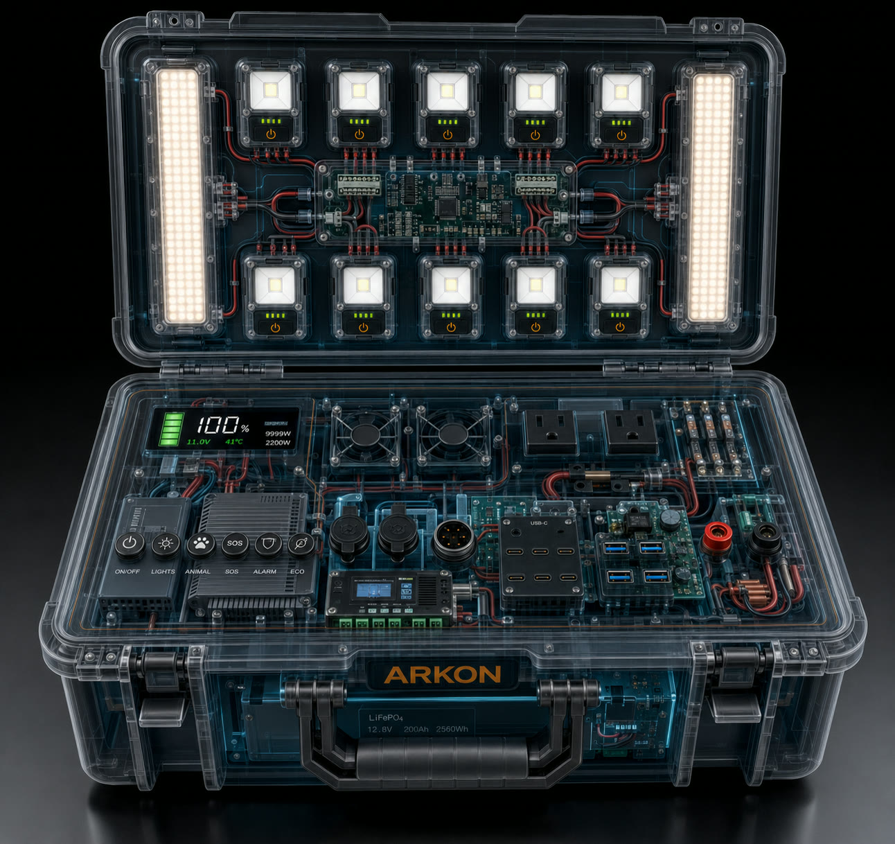
Cell block, BMS and inverter placement inside the sealed enclosure.
Rotary and button controls with the full output bank.
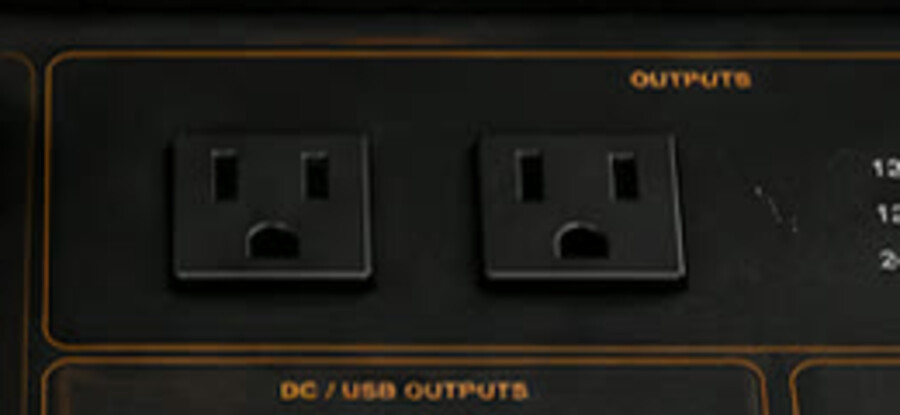
2 × 120 V pure-sine outlets rated 1,200 W continuous.
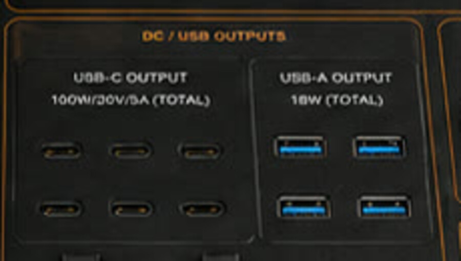
6 × USB-C PD and 4 × USB 3.0 fast-charge ports.
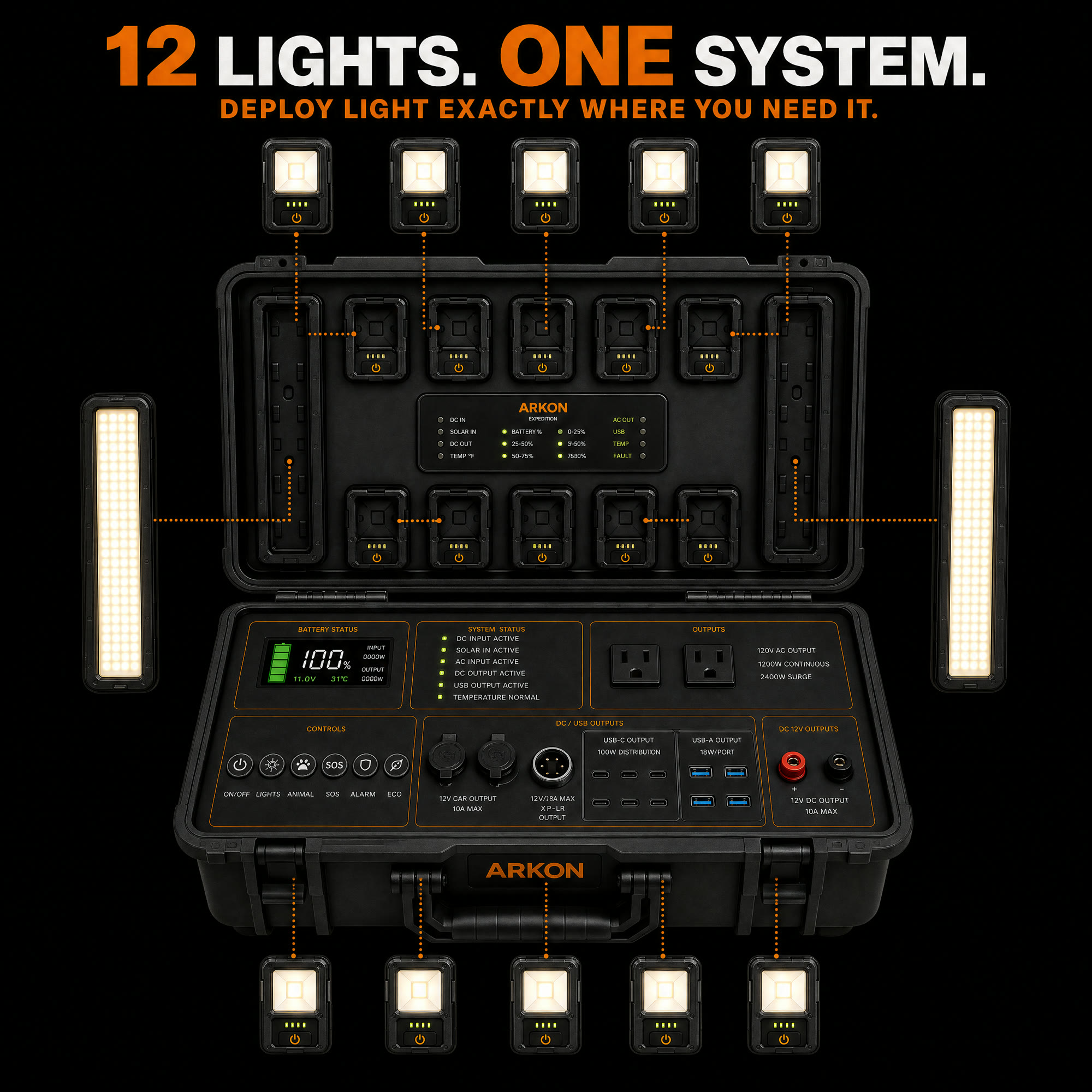
Coverage of the 10 modules plus 2 floodlight bars.
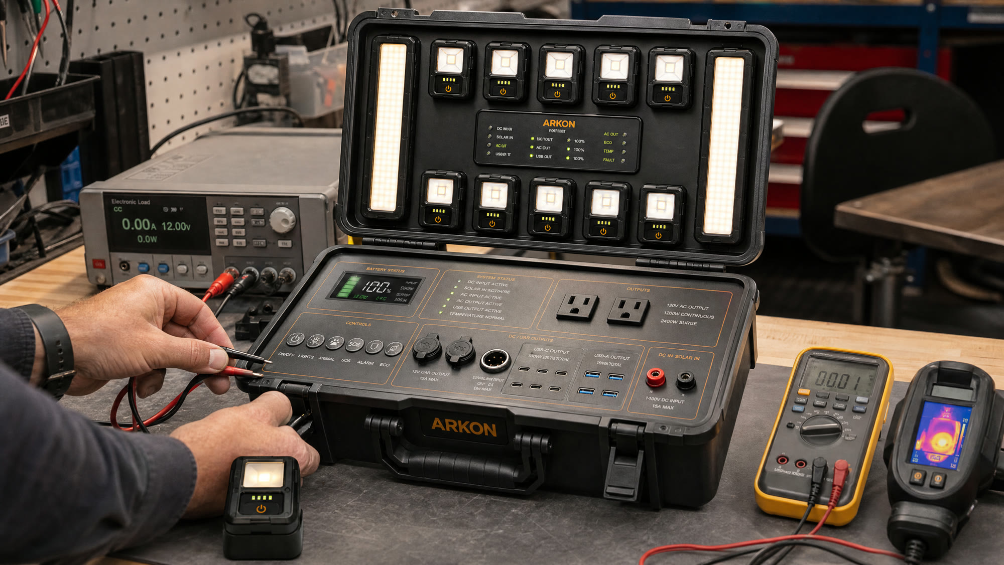
Real bench photography, published as each unit is built.
Everything above is a product visualization of the current design intent. The slots below are reserved for unretouched photographs of the physical hardware. We publish each one the day it is shot, with the date and what changed — no staged studio work, no renders.
Unretouched photo of the LiFePO4 cell block and BMS wired on the bench during capacity testing.
The 1,200 W inverter stage running a continuous load, with thermocouples and logging in frame.
A removable module being detached and re-docked in the lid, showing the real charge contacts.
First closed enclosure out of tooling, photographed before drop and ingress testing.
Reservation holders and waitlist subscribers receive each photo drop by email first.
What has to pass before anything ships.
Thermal & runtime
Continuous-load runs at 200 W, 600 W and 1,200 W with logged pack, inverter and enclosure temperatures.
Safety & certification
UN 38.3 transport testing, FCC emissions, UL or equivalent electrical safety, IP validation for the closed case.
Field validation
Cold-start behaviour, solar recharge in real daylight, and repeated open/deploy/pack cycles in the field.
From bench prototype to backer shipment.
- Stage 01 · 2026Concept & system architecture
Energy budget, output topology, lighting array layout and enclosure format defined. Product visualizations published.
- Stage 02 · NowEVT — engineering validation
Breadboard pack, inverter and BMS bench testing. Light module docking and charge circuit iterations.
- Stage 03 · Q1 2027DVT — design validation
Tooling-representative enclosure, full electrical validation, thermal soak, drop and ingress testing.
- Stage 04 · Q2 2027Certification & PVT
FCC, UN 38.3, electrical safety and IP certification, followed by a production-validation build.
- Stage 05 · Q3 2027Mass production & shipping
First production run, QC sampling and backer shipments beginning with Series 01 tiers.
Dates depend on completing certification and production. If a milestone slips, reservation holders and backers hear it from us first.
Reserve for $10